
ELLIOT'S CISCO NOTES
for future reference by me for me
lesson 3
lesson 4
lesson 5
lesson 6
lesson 3
network protocol overview
network communications protocol
allows two or more devices to communicate over one or more networks.
examples include ip, tcp, http
network security protocols
secures data to provide authentication, integrity, and encryption
examples include ssh, ssl, tsl
routing protocols
allows routers to exchange route information, compare it, and select the quickest option availible
examples include ospf, bgp
service discovery protocol
used for the automatic detection of devices or services
examples include dhcp, dns
general terms
network protocol suite
a group of inter related protocols necessary to perform a communication function
open standard protocol suite
freely available, can be used by any vendor on their hardware
standards based protocol suite
endorsed by the networking industry, and approved by a standards organization. insures that products from different origin can interoperate
tcp/ip layers
4 - application: represents data to users, plus encoding and dialog control
3 - transport: supports communication between various devices across diverse networks
2 - internet: determines the best path through the network
1 - network access: controls the hardware devices and media that make up the network
tcp/ip layers examples
(// means subcategory, //// means item in said subcategory)
application layer
// name system
////DNS [domain name system]
*
// host config
//// dhcpv4
//// dhcpv6
//// slaac
*
//// smtp
//// pop3
//// imap
*
// file transfer
//// ftp [file transfer protocol]
//// sftp
//// tftp
*
// web and web service
//// http
//// https
//// rest
transport layer
// connection
//// tcp
*
// connectionless
//// udp
internet layer
// internet protocol
//// ipv4
//// ipv6
//// nat
*
// messaging
//// icmpv4
//// icmpv6
//// icmpv6 nd
*
// routing protocols
//// ospf
//// eigrp
//// bgp
network access layer
// address resolution
//// arp
*
// data link protocols
//// ethernet
//// wlan
application -> transport -> internet -> network access
content layer -> rules layer -> physical layer
computer receiving: ethernet -> ip -> tcp -> data
computer encapsulating: data -> tcp -> ip -> ethernet
osi model layers
7 - application: contains protocols used for process-to-process communications
6 - presentation: provides representaions of data being transferred between the application layer
5 - session: provides services to the presentation layer to organize its data exchange
4 - transport: defines services to segment, transfer, and reassemble data between end devices
3 - network: exchanges individual pieces of data over the network between end devices
2 - data link: describes methods for exchanging data frames between devices over a common media
1 - physical: decribes the mechanical, electrical, functional, and procedural means to activate, maintain, and de-activate physical connections for a bit transmission to and from a network device
ip addresses
there are two parts to an ip address: the network and host portion
network portion[prefix]: the left most part of the address. indicates what network the device is on. all devices on the same network have the same network portion,
host portion[interface id]: remaining part of the address. identifies a specific device on the network. this portion is unique to each device.
example: 123.456.7.890
123.456.7. is the network portion
890 is the host portion
subnet mask divides the 2
mac versus ip
mac: identifies devices locally
ip: identifies devices globally
enable secret: gives extra security to enable password
enable password: priv exec mode, global ect
lesson 4: physical layer
the physical layer sits at the bottom of the osi stack, and is the primary foundation of the network.
4.1 == purpose of the physical layer
describes the purpose and functions of the physical layer in the network!!
// 4.1.1 == the physical connection
a physical connection can be wired or wireless using radiowaves!! very cool
while wired connections are connected with real cables, devices on a wireless network must be connected to a wireless AP [access point] or router
NICs [network interface cards [a physical chip in the device]] connect a device to the network. ethernet NICs are used for wired connections, and wlan NICs are used for wireless. an end device may have one or both of these.
// 4.1.2 == the physical layer
the osi physical layer allows the bits that make up the data link layer frame to be transported across the network media [wires or air]
this layer takes a complete frame from the data link layer and encodes it as a series [not all at once!!] of signals that are sent to the local media [wires or air]
PDU: protocol data unit; a basic unit of communication between devices, holds all those headers. ex, frames, packets
// frames vs packets vs segments
segments: split up data; the first step of packaging
packets: add addresses for routing; the second step
frames: prepare data for physical transmission; the final step
4.2 == physical layer characteristics
describes characteristics of the physical layer woah
// 4.2.1 == physical layer standards
the physical layer consists of electronic circuits, media [wires and air], and connectors. all of these components must met certain standards.
// 4.2.2 == physical components
the physical layer standards address physical components, encoding, and signalling
physical components are the electronic hardware, media [wires or air], and other connectors that send bit-representing signals
components like nics, interfaces, connectors, cable materials, and cable designs all must meet these standards
// 4.2.3 == encoding
encoding [or line encoding] is a method of converting data bits into a predefined 'code'. these codes are groups of bits used to make a predictable pattern that can be read by both the sending device and the recieving device
simply, its a method used to represent digital information, like how variables represent data in javascript [to natalia: i know you dont know javascript so this will go right over your head lolol]
ex. manchester encoding [used by older ethernet standards] == high to low voltage equals a 0, while low to high equals a 1
// 4.2.4 == signaling
the physical layer has to make the signals [electrical, optical, wireless] that represent the 1/0 binary on the media [wires or air]
the way that the bits are represented is called the signaling method. the layer's standards must tell what kind of signal means a 1 and what means a 0. think morse code
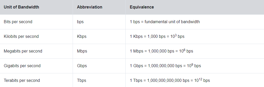
// 4.2.5 == bandwidth
data transfer is mostly discussed in terms of bandwidth
bandwidth is the capacity at which a medium can carry data [simply how mush data from a can get to b in a certain amount of time]
typically measured in kbps, mbps, or gbps. remember, the 'b' stands for bits, not bytes
a single bit is a boolean value [0/1]. a byte is 8 bits.
what can determine the bandwidth of a network you may ask?
* properties of the physical media [the connection [wires or air]]
* the systems that signal and detect network signals
* the law of physics
// 4.2.6 == bandwidth technology
what measures good bandwidth? latency, thoughtput, and goodput of course!!!!!!!
latency means the amount of time [+ delays] that it takes for data to travel from a to b
thoughtput means the number of bits transferred over a given period of time
* thoughtput can be pretty fast, but never faster than the slowest link in the transfer path
however, due to a few factors, thoughtput mostly never matches the specified bandwidth given. its usually lower than bandwidth sadly
* amount of traffic, type of traffic, latency [wait time] created by amount of devices between a and b
goodput means the amount of usable data transferred over a certain amount of time
it's pretty much thoughtput minus the traffic of many steps like encapsulation and transmitted bits
from highest to lowest, [bandwidth] > [thoughtput] > [goodput]
4.3 == copper cabling
cabling of the copper ooh
// 4.3.1 == characteristics of copper cabling
copper cables are the most common network cable. they are cheap, easy to install, and have low resistance to electrical currents
however, it is limited by distance and signal interference
data is transmitted through these cables as electrical pulses. a detector [in the network interface] of a destionation device has to recieve a signal that can be decoded to match the sent signal
however, the farther the signal travels, the more it deteriorates. [this is called signal attenuation]
because of this, all copper wiring must follow strict distance limitations
interference in timing and voltage values is also possible from two other sources:
* electromagnetic interference [EMI]: can distort and corrupt the data signals being sent due to radio waves and electromagnetic devices, such as lights or motors
* radio frequency interference [RFI]: same as emi
* crosstalk: a disturbance caused by the electric or magnetic fields of data on one wire to an ajacent wire. in telephone circuits, if this happens, you can hear the other signal's conversation. when a current flows through the wire, it creates a small circular magnetic field around itself, which can be picked up by other wires
* to counter emi and rfi, some kinds of wires are wrapped in a metallic shielding and need to be grounded
* to counter crosstalk, some kinds of wires have opposing circuit wire pairs twisted together, which prevents the crosstalk
you can also decrease the risk of electric noise by choosing the right cable type, designing the cable infrastructure to avoid known interference in a building's structure, and using the right cabling techniques such as correct handling and termination
// 4.3.2 == types of copper cabling
there are 3 kinds of copper cabling!!!!!!!!!
// 4.3.3 == unshielded twisted-pair [UTP]
utp is the most common networking media!
utp, terminated with rj-45 connectors, is used for interconnecting network hosts with devices like switches and routers
termination: connecting the cable to a device
in lans, utp cables have 4 pairs of color-coded wires that are twisted together and encased in a flexible plastic sheath that protects from damage a little bit. [the wire twisting helps protect against crosstalk]
the color coding identifies the individual pairs and wires and helps with termination
// 4.3.4 == shielded twisted-pair [STP]
stp provide better noise protection than the above utp. however, stp is much more pricy and harder to install
like utp, stp also use rj-45 connectors
stp combine the shielding techniques to counter emi and rfi, and have wiretwisting to fight against crosstalk
shielding: the shit on the outside of the cable
to use the shielding to its full extent, stp cables are terminated with special shielded stp data connectors
if the cable isnt grounded properly, the shield might make like an antenna and pickup unwanted signals
// 4.3.5 == coaxial cable
nicknamed coax, this cable gets its name from its two connectors that share the same axis
they consist of the following:
* a copper conductor where the signals flow [the main cabling in the center]
* a layer of flexible plastic insulation that goes around the copper conductor
* the insulation is surrounded by a woven copper braid, or a metallic foil, that acts as the second wire in the ciruit or as a shield for the conductor
* a cable jacket to protect a bit against physical damage
theres lots of different kinds of connectors used with coax cables; bnc, n type, and f type for example
while utp has replaced coax in most situations, coax is still used in wireless and cable internet installations
4.4 == utp cabling
more unshielded twisted pair cables!!! couldnt be happier
// 4.4.1 == properties of utp cabling
utp does not use shielding to prevent crosstalk, but it does use 2 other methods:
* cancellation: wires are paired while in a circuit, which causes their magnetic fields to oppose eachothers chargewise, cancelling out crosstalk
* varying twist numbers per wire pair: the number of twists in each wire pair is varied. each colored pair is twisted a different amount of times
// 4.4.2 == utp cabling standards and connectors
utp cabling must conform to stanrdards given by the tia/eia
there are 8 different categories of copper cabling. the higher the category, the better the ability to carry higher bandwidth rates
category 5e is currently considered the minimum, whereas category 6 is the current recommended type for new installations
male components are the plugs, while female components are the sockets
// 4.4.3 == straight-through and crossover utp cables
situations may require utp cables to be wired differently. this means that the wires must be connected in different orders to different sets of pins in the rj-45
the two main cable types:
* ethernet straight-through: the most common type, is used to interconnect a host to a switch and a switch to a router
* ethernet crossover: a cable used to interconnect similar devices, like a switch to a switch or a router to a router. these are considered legacy nowadays
[* rollover cable: used to connect a cisco workstation to a router or switch]
the most common connectivity error is using one of these cables incorrectly, so device connections should always be checked
| CABLE TYPE | STANDARD | APPLICATION |
|---|---|---|
| ethernet straight-through | both ends either t568a or t568b | connects a network host to a network device like a switch |
| ethernet crossover | one end t568a one end t568b | connects 2 network hosts or 2 network devices |
| rollover | cisco proprietary | connects a workstation to a router via adapter |
4.5 == fiber optic cabling
delicious
// 4.5.1 == properties of fiber optic cabling
is better than copper cables, but is very pricy!!
these cool wires can transmit data over longer distances and at faster bandwidth, and are immune to emi and rfi
optical fiber is actually an very very very thin piece of flexible glass, used to send bits encoded as light pulses
// 4.5.2 == types of fiber media
2 kinds!! single mode fiber [SMF] and multimode fiber [MMF]
single mode fiber produces a single straight path for the light, whereas multimode allows multiple paths for the light
however, mmf has more dispersion than smf, so it can only travel up to 500 meters before signal loss
dispersion: how far the light can spread out in the wire
// 4.5.3 == fiber optic cabling usage
fiber optic cabling is used in 4 kinds of industries!!
* enterprise networks: used for backbone cabling and interconnecting infrastructure devices
* fiber to the home [FTTH]: used for always-on broadband services to homes and small buisnesses
* long haul networks: used by service providers to connect far away places to eachother
* submarine cable networks: used for high speed, high capacity connections capable of surviving underwater
// 4.5.4 == fiber optic connectors
a connector terminates the end of a fiber optic. there's many kinds avaliable, but the only differences are size and wiring
some kinds include:
* straight tip [st]: twist on / twist off type locking
* subscriber connector [sc]: also called square connectors. uses push pull locking
* lucent connector [lc] simplex: smaller sc connector. also called little or local connectors
* duplex multimode lc: a duplex version of an lc
// 4.5.5 == fiber patch cords
fiber patch cords are required for interconnecting infrastructure devices
yellow cord means it's a single mode, and orange/aqua mean it's a multimode
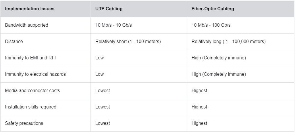
// 4.5.6 == fiber versus copper
fiber is primarily used as a backbone for high traffic, point to point connections. it is also used for interconnection of buildings in multi-building campuses
4.6 == wireless media
// 4.6.1 == properties of wireless media
wireless media carries electromagentic signals that represent bits using radio or micro waves
wireless media provides the best mobility out of all media!!
however limitations are present;
* coverage area: building materials and terrain [like mountains] can limit coverage
* interference: wireless media can be easily disrupted by common devices, like cordless phones
* security: any knowledgeable unauthorized user can gain access to any transmission made [hackermode!!!]
* shared medium: wlans [wi-fis] operate in half duplex, meaning only one device can send or receive at a time. many users using the wlan may experience slower bandwidth
// 4.6.2 == types of wireless media
wireless standards set by the ieee include:
* wifi [ieee 802.11]: uses a condition based protocol called 'carrier sense multiple access / collision avoidance' [CSMA/CA], meaning that if one nic is transmitting, other nics must wait until it is finished.
* bluetooth [ieee 802.15]: aka a wireless personal area network [WPAN]. range from 1-100 meters
* wimax [ieee 802.16]: stands for mr worldwide interoperability for microwave access. uses point to multipoint topology to provide broadband access
* zigbee [ieee 802.15.4]: used for low data rate and low power communications. used for things that need short range, low data and long battery life [my nokia phone versus like an iphone 18]
// 4.6.3 == wireless lan
wlan requires 2 network devices [another list!!! ohemgee]
* wireless access point [ap not wap sadly thad be really funnie]: concentrates wireless signals and connects to copper-based network infrastructure. integrates the function of a router, switch, and ap into a single fingle
* wireless nic adapters: provides wireless communication capability to network hosts
lesson 5: number systems
we will be learning about binary and hexidecimals here!!!
5.1 == binary number system
// 5.1.1 == binary and ipv4 addresses
ipv4 addresses are shown in binary
most network administrators convert these to decimal, because it is easier to read
addresses contain a string of 32 bits, devided into 4 sections called octets. each octet contains a byte seperated with a dot
// 5.1.2 == video yurrr
decimal is base 10, while binary is base 2
decimal ex.: 10, 100, 1000
binary ex.: 1, 2, 4, 8, 16
ip address octets represent the amount of a power of 2 between 0 and 7, starting at 7. they are all added together, making that octet
to make binary from a decimal, starting at 128, go down the list and subtract and count up the number of subtractions
7-0: 128, 64, 32, 16, 8, 4, 2, 1
// 5.1.3 == binary positional notation
big phat example
| position value | 128 | 64 | 32 | 16 | 8 | 4 | 2 | 1 |
|---|---|---|---|---|---|---|---|---|
| binary number [11000000] | 1 | 1 | 0 | 0 | 0 | 0 | 0 | 0 |
| add em up... | 128 | +64 | +0 | +0 | +0 | +0 | +0 | +0 |
| reslut | 192 |
5.2 == hexadecimal number system
// 5.2.1 == hexadecimal and ipv6 addresses
while ipv4 addresses use binary, v6 and ethernet mac use hexidecimal.
hexadecimal uses a base 16 system. this uses the digits 0-9 and letters a-f.
| decimal | binary | hexadecimal |
|---|---|---|
| 0 | 0000 | 0 |
| 1 | 0001 | 1 |
| 2 | 0010 | 2 |
| 3 | 0011 | 3 |
| 4 | 0100 | 4 |
| 5 | 0101 | 5 |
| 6 | 0110 | 6 |
| 7 | 0111 | 7 |
| 8 | 1000 | 8 |
| 9 | 1001 | 9 |
| 10 | 1010 | a |
| 11 | 1011 | b |
| 12 | 1100 | c |
| 13 | 1101 | d |
| 14 | 1110 | e |
| 15 | 1111 | f |
these addresses are 128 bits, and each 4 bits is represented by one hexadecimal digit. this totals 32 hexadecimal digits.
also not case sensitive!!
ipv6 addresses are formatted with a ':' between each 4 digits. a hextet means 4 hexadecimal values.
// 5.2.3 == decimal to hexadecimal
* first, convert the decimal number to 8 bit binary strings
* divide the strings into groups of 4 from the right
* convert each of the 4 binary digits into hexadecimal
ex with the number 168
** 168 in binary is 10101000
** 10101000 can be split into 1010 1000
** 1010 is a and 1000 is 8
** answer: a8!!
// 5.2.4 == hexadecimal to decimal
do the above backwards!!! hex -> binary -> decimal
lesson 6: the data link layer
6.1 == the purpose of the data link layer
// 6.1.1 == the data link layer
the data link layer prepares network data for the physical network in the physical layer!
this layer is responsible for nic to nic communications.
[remember: nic stands for network interface card!!]
the data layer link does all of the following:
* lets upper layers access the media, because the upper layers have no clue what type of media is being used
* accepts layer 3 packets [ipv4 or v6] and encapsulates them into layer 2 frames
* controls how data is sent and received over the media
* exchanges frames with endpoints over the network
* recieved encapsulated data [usually layer 3 packets] and sends them to the proper upper-layer protocol
* detects errors and rejects corrupt frames
nodes: devices that can get, make, store, or send data along a communications path.
these can be end devices [ex. laptop] or an intermediary device [switch].
with no data link layer, network layer protocols like ip would have to adapt to each kind of media connected.
// 6.1.2 == ieee 802 lan/man sata link sublayers
what the fuck does that mean
these standards are specific to ethernet lan, wlan, wpan, and other types of area network.
it's basically just the two halves of the data link layer.
the two sublayers are:
* logical link control [llc]: this ieee 802.2 sublayer talks with the networking software on the upper layers and the device hardware on the lower layers.
it writes information to frames that tells it what networking protocol is being used for the frame.
this lets multiple layer 3 protocols use the same network interface and media.
[in short, it takes the network protocol data, and gives it layer 2 control information to help it get to it's node.]
* media access control [mac]: implements this sublayer [ieee 802.3, .11, .15] in the hardware.
it is responsible for encapsulation and mac.
it also provides data link layer addressing and is a part of various physical layer technologies.
[in short, it controls the nic and other hardware that sends or gets data on the lan/man medium.]
but wait!! the mac layer can do so much more!!
it can do...
-- frame delimiting, which provides important delimiters to identify fields within a frame. this provides synchronation between the sending and recieving nodes.
[note-- delimiters are just a character that marks the beguinning and/or end of something. like the p and /p in html.]
-- addressing, which just gives a frame source and destination addresses for sending the layer 2 frame between devices.
-- error detection, which includes a trailer used to detect transmission errors.
[note-- trailers are control information sent at the end of a data transmission.]
the mac sublayer also provides media access control [also called mac] that lets devices communicate over a half-duplex. full-duplex do not require access control.
note-- man stands for metropolitan area network.
// 6.1.3 == providing access to media
// 6.1.4 == data link layer standards
6.2 == topologies
// 6.2.1 == physical and logical topologies
2 kinds 2 kinds 2 kinds 2 kinds 2 kinds:
-- physical topology: identifies physical connections [like wires] and how and how all the devices are connected. sometimes specifies rooms or locations.
-- logical topology == shows how frames transfer from one node to another in a visual medium. sometimes specifies device labels and layer 3 ip addresses.
[in short: physical = what we see, logical = what the computer sees]
// 6.2.2 == wan topologies
wans are interconnected in 3 ways:
** point to point: one wan to another wan
** hub and spoke: one wan to many wans
** mesh: many wans connected to eachother
// 6.2.3 == point to point wan topologies
as said above, point to point directly connects two nodes.
however, nodes do not nessesarily have to share their media with other hosts.
in point to point protocol [ppp], a node does not have to think about where the information needs to go, because theres only one possibility.
a source [start] and destination [end] node can actually be indirectly connected over multiple intermediary devices.
what's cool is that in this situation, the logical topology does not change, because the point to point connection is still the same.
// 6.2.4 == lan topologies
in multiaccess lan, end devices are connected to eachother via star or extended star topologies
star topologies look like a *, with devices at the end of each line, but no end device in the middle. in the middle would instead be an intermediary device, like an ethernet switch.
extended star topologies look like a *-*, with 2 star topologies connected via multiple ethernet switches.
theres a couple legacy toplogies as well. these arn't frequently used anymore, but are still good to be aware of nonetheless.
** bus topologies involve all end devices chained together, and terminated at each end. this was done via coax cables.
** ring topologies involve all end devices linked together in a ring, human centipede style. this does not need to be terminated.
// 6.2.5 == half and full duplex communication
the daring duo, half duplex and full duplex!!!
** half duplex: both devices can send and receive, but not at the same time.
** full duplex: both devices can send and receive at the same time.
to the top ^